I stumbled across this project after watching a YouTube video on voltage multipliers. Basically, these circuits use DC voltage as the input, oscillate the voltage and then multiplies the voltage through a clever use of simple components. After a bit of searching, I came up with this ultra-simple design to create a basic stun gun with very little effort.
First, lets talk about what you need to purchase. All of these items are from Amazon.
- 1 – High Voltage Generator
- 1 – 18650 Battery Holder
- 1 – Momentary button
- 1 – 18650 battery
- 2 – 3mm x 15mm screws
- STL FILES to print
Second, you need the STL files (or design your own). The model I created is very basic and not very creative, but I was looking to create something functional vs focusing on the design. Feel free to create your own model and share with the community. The only considerations to designing for this project is to have room for the battery, button and HV generator. So, you could create something that looks like a traditional stun gun or tazer. Or, remix an existing prop gun (i.e. Fallout Thirst Zapper?) and add the electronics to it.
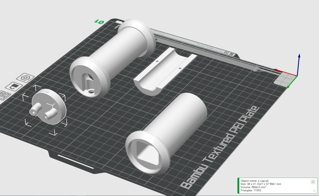
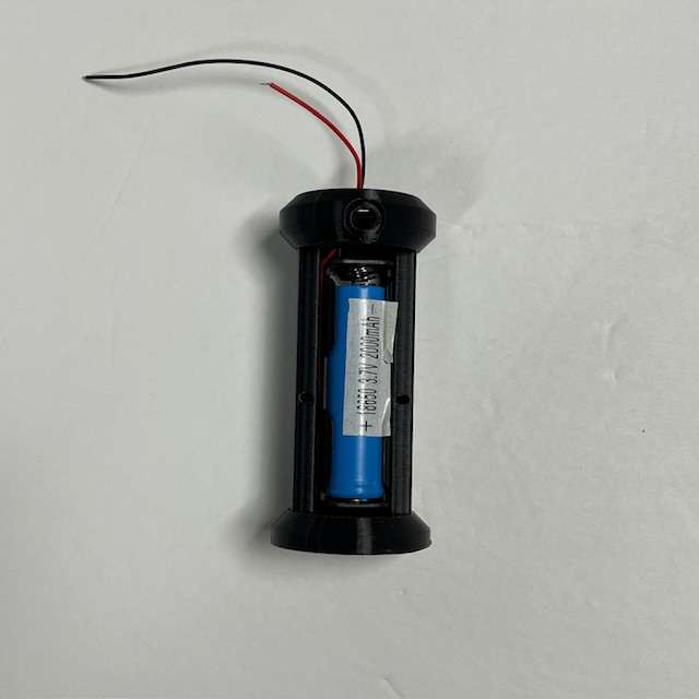
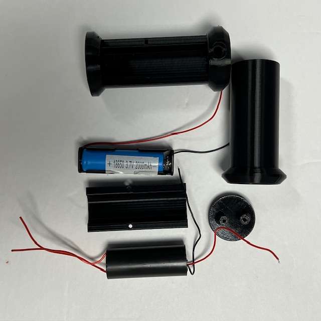
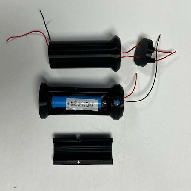
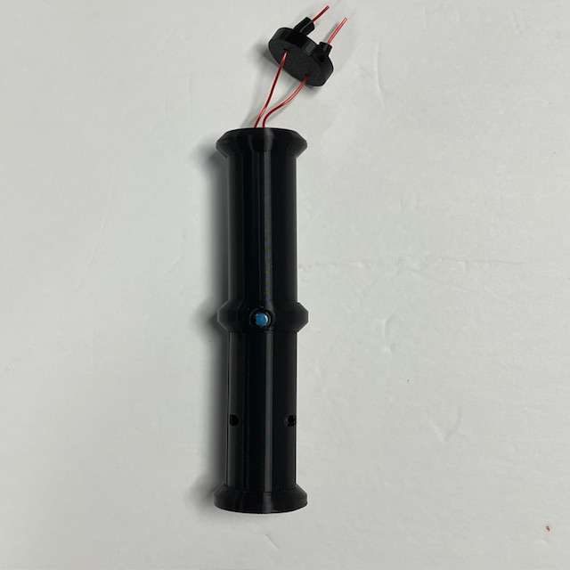
Once you’ve printed the parts, the rest is pretty simple and can be assembled in 10 minutes or so. In the photo above you will see 4 pieces. In the upper left is the battery holder. To its right is the battery door that attaches with 2 – 3mm screws. The component in the bottom right is where the HV generator will go. Finally, the last piece goes on the top of the HV generator holder and holds the wires apart from each other. You will need to trim the wires to the appropriate length but do this as your last step.
- Take the battery holder and insert the 18650 battery holder from Amazon. The wires should be routed so they exit the top.
- With the black wire exiting the top of the battery holder and solder it to one side of the push button switch.
- Insert the HV generator into the HV generator holder with the two red wires coming out the top. The top has the wider rim around it. This means that the black and red wire will exit the bottom of the HV generator holder.
- Solder the black wire from the HV generator to the other side of the push button switch.
- Solder the two red wires to each other to complete the circuit.
- Put the button into the hold so it extends out the side. Instead of using the provided nut, I chose to use hot glue to hold the switch in place. This allowed me to have less of the button protruding.
- Now, assemble the battery holder and HV holder together. They should fit snugly together. For now, do not apply any glue, but for final assembly you can use some super glue or other glue to make it permenant.
- The top should have the two red wires exiting the HV holder. Using the top insert (lower left in the photo above), push the two red wires through the holes so they exit out the top. You can now press the top piece into the recessed portion of the HV holder.
At this point you should have a fully assembled unit. Add your battery and test that everything works as it should.
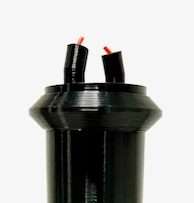
** NOTE ** The spark is generated between the red wires. The size and frequency of the sparks will be determined by the distance between the wires. If they are too far apart, no spark will be generated and you’ll hear a high pitched noise. - Once you’ve tested everything and it’s working, you can do the final assembly. Add glue between the battery and HV portions; then between the HV portion and the top. You’ll need to trim the red wires so the extend past the top by a short amount (a mm or two is fine).
That’s it! Please feel free to leave a comment below. And, if you do remix / re-design a better looking unit, please do share it with me.

Leave a Reply